All about Carbon Fiber
Advantages and Disadvantages of Carbon Fiber Composites in Bicycles
Advantages and Disadvantages of Carbon Fiber Composites in Bicycles
Carbon fiber composite materials have revolutionized the bicycle industry, offering exceptional performance characteristics. However, these benefits come with certain trade-offs. Below is an outline of the advantages and disadvantages of using carbon fiber in bicycles.
Advantages
-
Lightweight
Carbon fiber is significantly lighter than traditional materials like aluminum or steel, making it ideal for high-performance road, mountain, and triathlon bikes.
-
High Strength-to-Weight Ratio
Despite its light weight, carbon fiber is incredibly strong, offering excellent load-bearing capacity and durability under normal riding conditions. It is possible to achieve strength-to-weight ratios 4-10 times that of metals.
-
Customizable Stiffness and Flex
By layering the carbon fiber in specific orientations (lay-up), manufacturers can fine-tune the stiffness and compliance of different parts of the frame for optimal performance and comfort.
-
Aerodynamic Design
Carbon fiber allows for complex shapes and smooth surfaces, enabling manufacturers to create highly aerodynamic frames with minimal drag.
-
Corrosion Resistance
Unlike metals, carbon fiber does not corrode, making it a long-lasting material in various environmental conditions.
-
Vibration Dampening
Carbon fiber has natural vibration-dampening properties, providing a smoother ride and reducing fatigue for the rider.
Disadvantages
-
Cost & Labour Intensive
Carbon fiber bicycles are more expensive to manufacture due to the high cost of raw materials and the labor-intensive production process.
-
Brittleness / Little to no warning before failure
While strong, carbon fiber can be brittle and is more susceptible to catastrophic failure under sudden impacts or extreme forces compared to metals, which tend to deform before breaking.
-
Difficult Repairs
Damage to carbon fiber frames, such as cracks or delamination, often requires specialized equipment and expertise to repair, making maintenance more complex and costly.
-
Moisture Sensitivity
Prolonged exposure to moisture can degrade the resin matrix in poorly manufactured composites, potentially reducing the material’s strength and stiffness.
-
Environmental Impact
Carbon fiber production is energy-intensive, and recycling options are limited compared to metals, raising concerns about its environmental sustainability.
-
Hidden Damage
Damage to carbon fiber can be impossible to detect with the naked eye and is often inside the material itself. This means specialist equipment and expertise is required to inspect and determine if it is safe to use.
Conclusion
Carbon fiber composites have become a cornerstone of modern bicycle design, offering unparalleled performance advantages for competitive and recreational riders alike. However, riders must weigh these benefits against the material's higher cost, repair challenges, and environmental considerations. For those seeking the ultimate combination of speed, comfort, and aesthetics, carbon fiber bicycles remain a leading choice.
A brief history of carbon fiber bikes
Many of today’s leading bicycle brands, such as Trek, Specialized, Giant, and Cannondale, were established during the cycling boom of the early 1970s.
In 1970, seven years after the carbon fiber production process was patented, Gerald O’Donovan of Carlton Cycles began experimenting with the material.
The first carbon fiber bicycle was unveiled at the Cycle and Motorcycle Show in Harrogate in 1971.
In 1975, Frank Appel, Richard Katner, Bill McCready, and Jeffrey Lindskoog of the F.H. Appel Company designed a carbon fiber bicycle frame. A year later, the ‘Graftek G-1,’ an aluminum-carbon fiber hybrid, was used by the 1976 U.S. Olympic team and subsequently made available to the public.

European companies began exploring composites in the early 1980s. In 1987, Giant launched the CADEX carbon fiber road bike, becoming the first bicycle manufacturer to use computer-aided design and mass production techniques for carbon fiber road bikes.
In 1989, Trek made a breakthrough by unveiling its first molded carbon fiber frame, the Trek 5000.
Carbon fiber gained popularity in the early 1990s after being introduced to professional cycling. Its lightweight properties, compared to steel frames of the time, quickly established it as the material of choice.
During the 1990s and early 2000s, carbon fiber was still considered an “exotic” material. However, advancements in manufacturing and reduced raw material costs have since fueled global demand, with an estimated 6.3 million units projected to be sold between 2020 and 2025.
Evolution of Carbon Fiber Bikes: Then vs. Now
When carbon fiber bicycles were first introduced in the late 1970s and early 1980s, they represented a revolutionary departure from traditional steel and aluminum frames. Early carbon fiber bikes, such as the iconic Kestrel 4000 or the Trek 5000, showcased the material’s potential for creating lightweight and aerodynamic designs. However, these pioneering models faced significant challenges in terms of manufacturing, durability, and performance consistency, as the technology and understanding of carbon composites were still in their infancy.
Between 2021 and 2025, an estimated 59.4 million new carbon bikes will be sold. Although no centralized records of carbon bike sales exist, it is believed that the number of carbon bikes currently "in use" is in the hundreds of millions.
Early Days of Carbon Fiber Bikes
-
Manufacturing Techniques: Early carbon fiber frames were often constructed using tube-to-tube bonding methods, where individual carbon tubes were glued together using metal lugs. This approach limited design flexibility and sometimes compromised strength at the joints.
-
Durability Issues: The initial lack of expertise in working with carbon composites led to concerns about fragility and failure. Frames were prone to cracks or delamination under stress, and quality control was inconsistent.
-
Performance: While the material offered significant weight savings compared to steel or aluminum, early carbon bikes lacked the refined ride quality and stiffness tuning that modern riders expect. The technology to optimize frame layups for specific performance characteristics was not yet developed.
- Cost: Carbon fiber bikes were prohibitively expensive, making them accessible only to elite athletes or wealthy enthusiasts.
Modern Carbon Fiber Bikes
Today, carbon fiber bikes are the gold standard in high-performance cycling, dominating the professional racing scene and becoming increasingly accessible to everyday riders. Advances in materials science, manufacturing processes, and design innovation have addressed many of the challenges of the early days.
-
Advanced Manufacturing: Modern carbon frames are typically made using monocoque construction, where the frame is molded as a single piece. This allows for seamless designs, improved strength, and greater aerodynamic efficiency. Automated processes and computer-controlled precision have significantly improved quality and consistency.
-
Tailored Performance: Engineers now use sophisticated layup techniques to customize stiffness, compliance, and weight distribution across different parts of the frame. This allows manufacturers to create bikes optimized for specific disciplines, such as climbing, sprinting, or endurance riding.
-
Durability and Longevity: Advances in resin formulations, fiber technology, and damage testing have greatly enhanced the durability of carbon bikes. Modern frames are designed to withstand impacts and resist fatigue, and improved inspection techniques help identify potential issues before they become critical.
-
Weight and Aerodynamics: Carbon fiber’s ability to be molded into any shape has led to groundbreaking aerodynamic designs, reducing drag and enhancing speed. At the same time, frame weights have dropped dramatically, with some road bike frames weighing less than 700 grams.
- Cost and Accessibility: While high-end models remain expensive, advancements in manufacturing have made carbon fiber bikes more affordable, with entry-level models providing excellent performance at reasonable prices.
Summary
The evolution of carbon fiber bikes from their early days to the present is a testament to the rapid progress in materials science and engineering. What was once an experimental and niche product has become the benchmark for performance and innovation in cycling, offering unparalleled strength, stiffness, and lightweight advantages that continue to push the boundaries of what’s possible on two wheels.
Carbon Bike Failures
Records of carbon fiber failures are scarce, largely due to challenges in reporting. Incidents are typically documented through hospital and police records, yet many victims of bicycle failures may not report to either.
Crashes, for instance, are estimated to account for only 6% of self-reported incidents resulting from mechanical or equipment failures. However, whether a crash occurs does not necessarily indicate the presence or absence of risk from damage or defects. These issues, depending on their type and severity, may lead to failure if not identified and addressed early.
As forensic expert Roman Beck explains, "because no one tracks how often carbon fiber fails, there's no way to determine how widespread the problem has become."
Identifying and assessing damage in carbon bikes is crucial, not only to minimize the risk of accidents or injuries but also to help owners protect their investments and extend the lifespan of their bikes.
What are carbon fiber composites ?
Composites are materials composed of two or more distinct constituents, each of which remains identifiable at a macroscopic level. In this system, one component serves as the reinforcing agent (fiber reinforcement), while the other acts as the binder (resin matrix). These components retain their individual properties and are separated by a detectable interface.
In bicycle manufacturing, composites are favored for their exceptional strength, stiffness, and relatively low weight. One key advantage of composites is their excellent inherent damage tolerance. Unlike metals, which are prone to corrosion, composites do not fail due to fatigue as long as they are not subjected to strains beyond a specific threshold.
However, composites are not without drawbacks. They can suffer from moisture ingress, which can weaken the matrix and reduce both compressive strength and stiffness over time.
How are carbon fiber filaments made ?
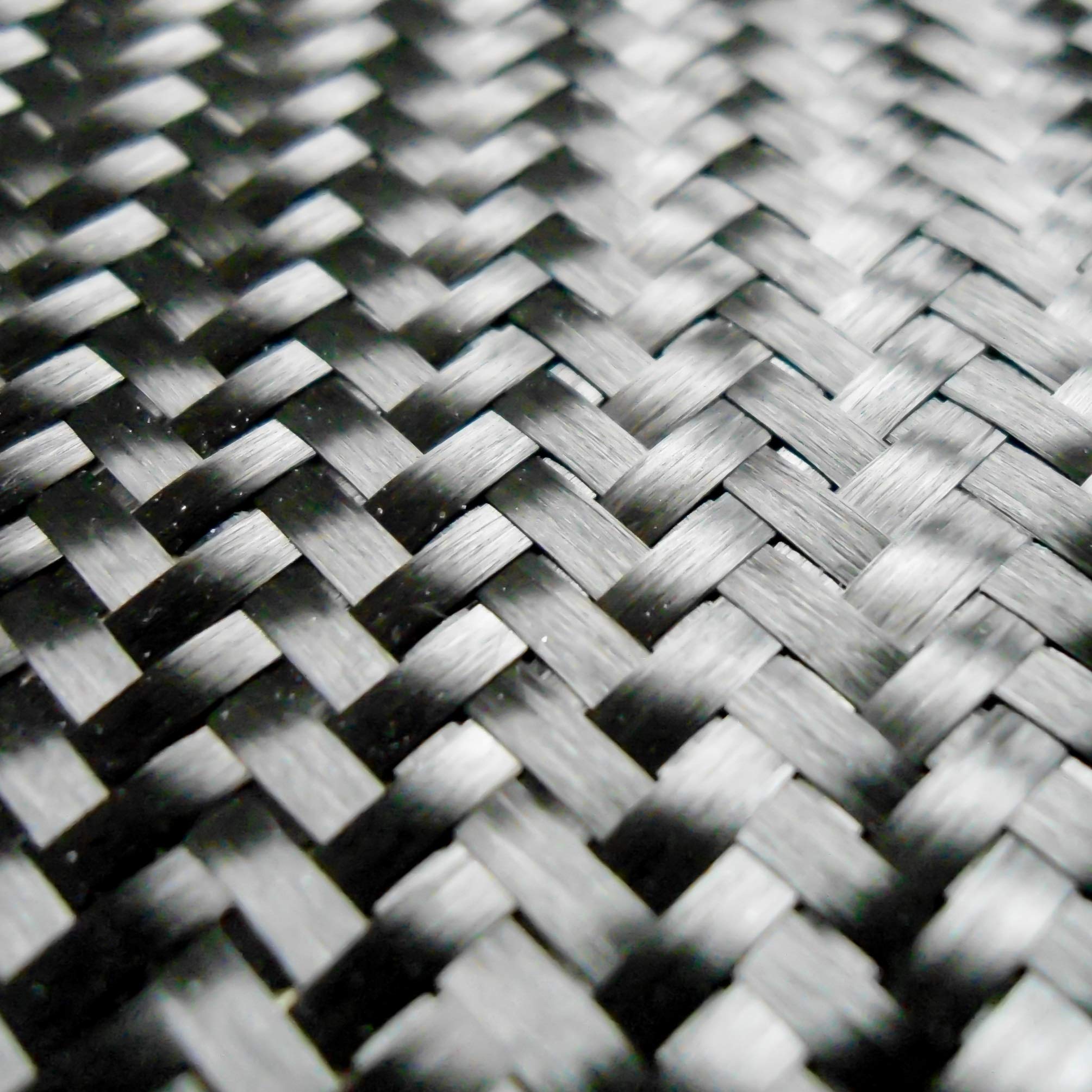
The basics of carbon fiber
Carbon fiber consists of thousands of tiny filaments within each strand. These strands are then woven into sheets or wound onto spools, which are the forms most commonly used.
From Polyacrylonitrile to High-Performance Material
Carbon fiber production is a highly technical process that transforms a precursor material, typically polyacrylonitrile (PAN), into long, thin fibers composed mostly of carbon atoms. The process involves several stages, including chemical treatment and heat processing, to create a material that is lightweight, strong, and stiff.

1. Precursor Preparation
The process begins with polyacrylonitrile (PAN), a synthetic polymer. PAN is preferred as the precursor for carbon fiber because its molecular structure—a long chain of carbon and nitrogen atoms—is ideal for forming the necessary carbon backbone during later processing stages.
-
Polymer Spinning:
- PAN is dissolved in a solvent to form a viscous solution.
- The solution is extruded through tiny spinnerets, forming long filaments.
- These filaments are collected and stretched into fibers, aligning the polymer chains to improve molecular orientation, which is crucial for the fiber’s final mechanical properties.
2. Stabilization
The PAN fibers are heated in air at temperatures between 200°C and 300°C to stabilize them chemically.
- Objective: Convert the linear polymer chains of PAN into a thermally stable structure.
-
Process:
- Oxygen reacts with the PAN, causing cross-linking between molecular chains.
- The fibers turn black and become non-melting, a critical step before carbonization.
- Outcome: Stabilized fibers with improved heat resistance.
3. Carbonization
In this stage, the stabilized fibers are subjected to extremely high temperatures between 1,000°C and 3,000°C in an inert atmosphere (typically nitrogen gas) to remove non-carbon elements like hydrogen, nitrogen, and oxygen.
- Objective: Convert the fiber to nearly pure carbon.
-
Process:
- As the fibers are heated, they lose mass due to the release of gases like water, carbon dioxide, and ammonia.
- The remaining carbon atoms realign into tightly packed, graphite-like structures that give carbon fiber its high strength and stiffness.
- Outcome: Fibers composed of about 92–99% carbon.

4. Surface Treatment
After carbonization, the fibers undergo surface treatment to enhance adhesion with the resin matrix used in composites.
- Objective: Improve bonding between the carbon fiber and the matrix material (e.g., epoxy resin).
-
Process:
- The fiber surface is oxidized using chemicals (e.g., nitric acid) or electrolytic processes to create functional groups.
- This increases surface roughness and introduces sites for chemical bonding.
5. Sizing
The treated fibers are coated with a protective layer, known as sizing.
- Objective: Protect the fibers during handling and weaving and improve compatibility with the matrix material.
-
Process:
- Fibers are coated with a polymer-based material, such as epoxy or urethane.
- This coating prevents damage to the fibers and ensures easier processing into composite materials.
6. Spooling
The finished carbon fibers are spun onto spools, ready for weaving into fabrics or incorporation into composite materials.
-
Final Properties:
- Carbon fibers have a diameter of about 5–10 micrometers.
- They are lightweight, incredibly strong, and stiff.
Summary of Key Steps:
- Precursor Preparation: Spinning PAN into fibers.
- Stabilization: Heating PAN in air to make it thermally stable.
- Carbonization: Heating in an inert environment to form carbon fibers.
- Surface Treatment: Enhancing fiber bonding properties.
- Sizing: Applying a protective coating.
- Spooling: Preparing the fibers for further use.
The resulting carbon fibers are then woven or molded with a resin matrix to create the strong, lightweight composites used in bicycles, aerospace, and other high-performance applications.

Types of carbon fiber
Composite manufacturing can be broadly classified into two categories based on how the fibers are treated and when the resin is introduced.
Category 1
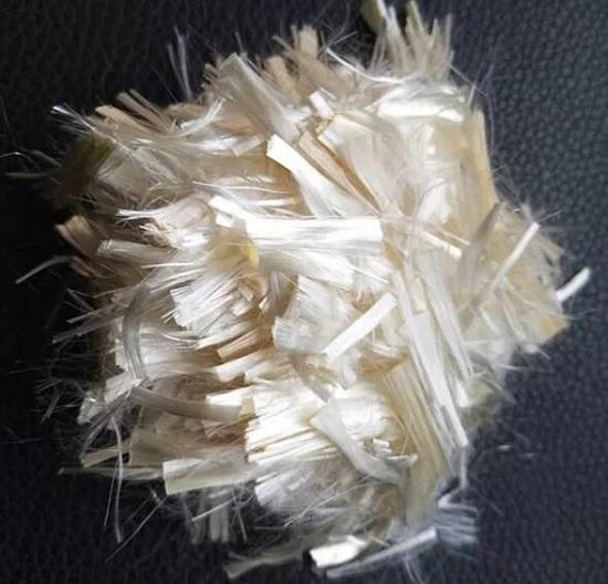
- Bare fibers
- Protected by binder or size
- Wet-out (resin application and encapsulation of filaments) during manufacture.

Loose fibers
Category 2
- Fibers pre-impregnated with resin.

- Unidirectional (One direction only), woven
Unidirectional


Important Notes
Basic Manufacture Steps
The basic process, regardless of the materials used, involves the following steps:
1. Lay-up: Stacking the ply materials, either manually or automatically.
2. Curing: Exposure to elevated temperatures and pressure, typically using an autoclave or similar equipment. This step includes:
-
-
- Heating, which reduces the viscosity of the resin.
- Thermal expansion of the tool.
- Vacuum application to remove volatiles.
- Pressure application, initiating laminate consolidation.
- Optional removal of the vacuum.
- Resin begins to gel, setting the part's geometry.
- Heating continues until the resin is fully cured.
- Controlled cooling of both the part and tool to prevent cracking of the resin matrix.
- Tool shrinks during cooling.
-
3. Post-cure: Final trimming, machining, and inspection of the components
Carbon fiber lay-up / Ply Orientation
Lay-up in carbon fiber manufacturing refers to the process of arranging layers of carbon fiber fabric or sheets in specific orientations to create a structure. Each layer, or "ply," is carefully positioned to achieve the desired strength, stiffness, and performance characteristics of the final product.
To facilitate the manufacturing process and ensure precise ply orientation, a "Warp (Ply) Clock" is used (refer to the image below). This clock is typically aligned with the X-axis of the part, which usually corresponds to the span-wise direction or the primary direction of the applied load. The alignment is clearly marked on the engineering drawing for the component.
In this system:
- 0° represents the X-axis.
- 90° represents the Y-axis.
- Positive (+) orientations are to the right of 0°.
- Negative (-) orientations are to the left of 0°.
In bicycle manufacturing, the most commonly used angles are 0° (in line), +45°, -45°, and 90° relative to the datum or axis. Additional angles may be utilized for specific applications or unique requirements.


Manufacturing Methods
Two commonly used manufacturing methods are:
-
Open molding
- Hand lay-up
- Spray-up
- Casting
- Filament winding
-
Closed molding
- Closed 'Bladder' Molding
- Vacuum Bag Molding
- Resin Transfer Molding
- Compression Molding
The choice of method depends on the required strength and the level of control over fiber orientation.
Key differences between the methods include:
- The achievable fiber volume,
- The precision in positioning fibers in specific orientations, and
- The overall cost.
Closed Mold Example (One half)

Manufacturing Methods - Open Molding
Open Molding
In open molding, raw materials, such as resins and fiber reinforcements, are exposed to air during the curing or hardening process. This method is relatively inexpensive, depending on the specific process used, especially when compared to closed molding.
Resin and fiber placement in open molding can be achieved through:
- Hand lay-up
- Spray-up
- Casting
- Filament winding
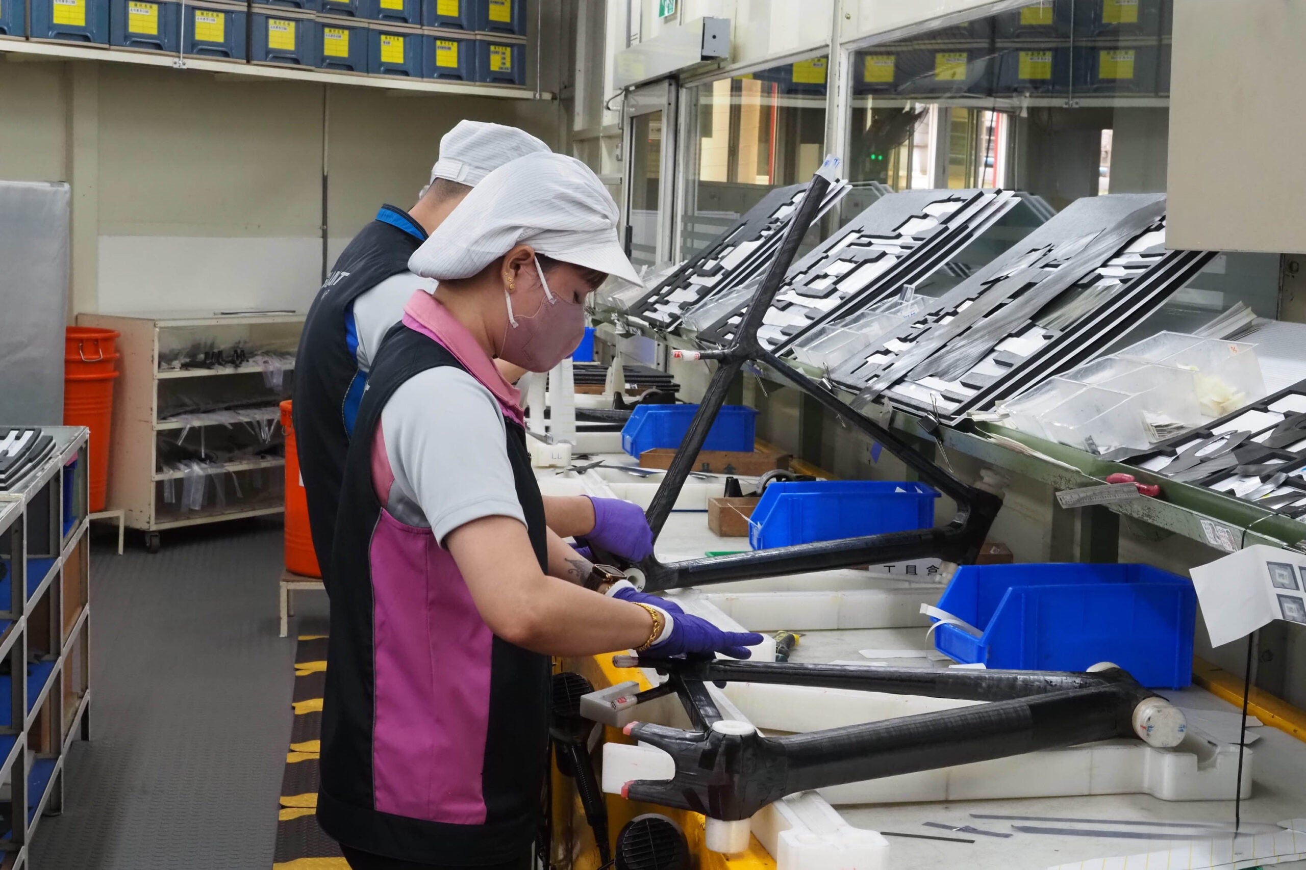
Hand Lay-up
Hand lay-up is a versatile method for creating composite products of various sizes, from very small to extremely large. While production volume per mold is relatively low, significant quantities can be achieved using multiple molds. This process is the simplest composite molding method, offering:
- Low-cost tooling
- Simple processing
- Flexibility in part sizes
Design changes can be made easily with minimal equipment investment. With skilled operators, it is possible to achieve good production rates and consistent quality.
Spray Lay-up
The spray lay-up process begins by applying a gel coat to the mold, which is allowed to cure. Continuous strand glass roving and resin are then fed through a chopper gun, depositing the resin-saturated chopped fibers onto the mold. The laminate is rolled to thoroughly saturate the fibers and compact the layers. Additional chopped laminates are added as needed for thickness.
Roll stock reinforcements, such as woven roving or knitted fabrics, can also be incorporated with the chopped laminates to enhance strength and performance.
Filament Winding
In filament winding, continuous strand roving is passed through a resin bath and wound onto a rotating mandrel. The roving feed is guided by a trolley that moves along the mandrel’s length, laying down the fibers in a predetermined geometric pattern to provide optimal strength in specific directions.
Once the required number of layers is applied, the laminate is cured on the mandrel. After curing, the finished part is removed from the mandrel. Filament winding equipment is also available for continuous axis winding, commonly used for producing pressure cylinders.
Manufacturing Methods - Closed Molding
Closed 'Bladder' Molding
In closed molding, raw materials (fibers and resin) cure inside a two-sided mold or within a vacuum bag, isolated from air. This process is typically automated and requires specialized equipment. Common closed molding processes include:
- Vacuum bag molding (hand lay-up)
- Resin transfer (injection) molding (hand lay-up), e.g., the Quickstep process
- Compression molding
Vacuum Bag Molding (Autoclave)
This process involves laying out unidirectional fibers or woven cloth to form flat sheets, which are then impregnated with a resin matrix and partially cured to a "tacky" B-stage. Lay-ups of multiple layers, oriented to suit load requirements, can be created by hand or automated methods.
Using prepreg materials ensures excellent fiber wet-out, even resin distribution, and high fiber volumes (up to 80%). The lay-up is placed on an open mold (commonly steel or composite) and vacuum bagged to consolidate the layers and remove volatiles during curing. The entire assembly is then placed in an autoclave, where heat and pressure cure the resin. This method produces parts with minimal porosity and excellent mechanical properties.
An additional, but very similar concept, method is called vacuum infusion and involves drawing a resin into the matrix using the vacuum.


Resin Transfer Molding (RTM)
RTM, also known as liquid molding or resin infusion, involves laying dry reinforcement material inside the mold. This allows for any combination of material and orientation, including 3-D reinforcements. The mold cavity determines the part's thickness.
Fast cycle times can be achieved with temperature-controlled tooling, and the process ranges from simple to highly automated. RTM accommodates a variety of tooling, from low-cost composite molds to temperature-controlled metal molds. Vacuum assistance can enhance resin flow, achieving a high resin-to-fiber ratio. This method is ideal for aerospace-grade composites, such as CFRP spars, often produced via the Quickstep process.
![]()
Compression Molding
In compression molding, a molding polymer is compressed into a preheated mold, conforming to the mold cavity and curing under applied heat and pressure.
The process can be automated, offering flexibility in part design, including features like inserts, ribs, bosses, and attachments, while delivering good surface finishes and reducing manufacturing costs.
With cycle times ranging from 1-6 minutes (longer than injection molding), compression molding is suitable for producing large, flat, or moderately curved parts.

Introduction
Understanding Potential Defects and Damage in Carbon Fiber
Carbon fiber is prized for its high strength, lightweight properties, and versatility. However, like any material, it is susceptible to defects and damage that can compromise its performance. Below is an introduction to the common types of issues that may arise in carbon fiber composites.
Location of Damage and Failure Risk

Manufacturing-induced defects can arise from various factors, including the manufacturing process itself, errors in layup (human factors), tooling design, or the component's design.
In-service damage is a broad term encompassing any damage sustained by the material during its use.
Impact damage specifically refers to cracks, chips, or other surface damage on painted areas caused by repeated impacts.


1. Broken Fibers
Broken fibers occur when individual carbon filaments within the composite structure are fractured due to excessive stress or impact. This can weaken the overall strength of the material and lead to localized failure.
2. Delamination
Delamination refers to the separation of the composite layers or plies. This damage typically results from poor bonding during manufacturing, impacts, or excessive stress. Delamination significantly reduces the structural integrity of the material.
3. Matrix Cracks
Matrix cracks are small fractures in the resin matrix, which binds the carbon fibers together. These cracks can spread under stress, allowing moisture to penetrate and further degrading the material.
4. Voids
Voids are small pockets of air trapped within the composite during manufacturing. These reduce the material's strength and stiffness and can act as initiation points for further damage.
5. Wrinkles
Wrinkles occur when the carbon fibers are misaligned or folded during the lay-up process. This defect weakens the composite by disrupting the uniform fiber orientation necessary for optimal load distribution.
6. Resin-Rich Areas
Resin-rich areas are regions with an excess of resin relative to fibers. While resin is essential for binding, excessive amounts can reduce the overall strength and lead to stress concentrations.
7. Debonding
Debonding happens when the bond between the carbon fibers and resin matrix fails. This defect compromises the load transfer between fibers, reducing the material's mechanical performance.
8. Foreign Objects
Foreign objects embedded in the composite during manufacturing, such as dust or debris, create weak points and can initiate cracks or other damage under stress.
9. Blisters
Blisters are raised areas caused by trapped gas or improper curing during manufacturing. They create stress concentrations and compromise the composite's structural integrity.
10. Porosity
Porosity refers to the presence of numerous small voids throughout the composite. High levels of porosity weaken the material, decrease its stiffness, and increase the risk of delamination.
Conclusion
Understanding these potential defects and damage types is critical for maintaining the performance and safety of carbon fiber components, especially in high-performance applications like bicycles. Regular inspections, proper manufacturing techniques, and early detection of issues can help mitigate risks and extend the lifespan of carbon fiber products.
Impact Damage
Understanding Impact Damage Propagation in Carbon Fiber Bicycle Frames
Carbon fiber bicycles are renowned for their strength and lightweight construction, but like any material, they are not immune to damage. Impact damage is one of the most significant threats to the structural integrity of carbon fiber frames, often propagating in ways that are not immediately visible.


Sources of Impact Damage
Impact damage can result from several factors, including:
- In-service fatigue: Repeated stress during normal use that weakens the material over time.
- Environmental factors: Exposure to moisture, temperature fluctuations, or UV radiation can exacerbate existing vulnerabilities.
- Maintenance activities: Poor handling during repairs or transportation can also lead to impact damage.
How Impact Damage Manifests
When a carbon fiber frame experiences an impact, the damage is rarely confined to the visible surface. The effects include:
- Surface Indentations: These are the most noticeable signs, such as dents or scratches at the point of impact.
-
Subsurface Damage: Beneath the surface, the damage can include:
- Cracking: Micro-cracks may form in the resin matrix or fibers.
- Delamination: Layers of carbon fiber laminate may separate, weakening the material.
- Disbonding: The bond between the frame’s skin and internal stiffeners can fail, significantly reducing structural integrity.
Characteristics of Damage Propagation
The pattern of damage from an impact typically forms a conical area radiating away from the point of contact. This conical zone includes:
- Micro-cracks: Tiny cracks that may coalesce over time, compromising load-bearing capabilities.
- Delaminations: Layers within the laminate separate, reducing stiffness and strength.
Hidden Dangers of Impact Damage
One of the most concerning aspects of impact damage is that subsurface damage is often more extensive than what appears on the surface. A small visible dent could mask:
- Large delaminated areas within the laminate.
- Disbonds between the carbon skin and internal stiffeners, which are critical for maintaining the frame’s structural integrity.
Long-term Effects
If left unchecked, impact damage can propagate over time due to in-service stresses, leading to:
- Reduced fatigue resistance.
- Catastrophic failure under load.
Prevention and Mitigation
To minimize the risks associated with impact damage:
- Inspect regularly: After any crash, fall, or significant impact, thoroughly inspect your bike for visible and hidden damage.
- Use protective measures: Frame protectors and proper handling during transport can reduce the likelihood of impacts.
- Seek expert evaluation: If you suspect damage, consult a professional who can perform non-destructive testing (NDT) to assess the frame’s condition.
By understanding how impact damage propagates in carbon fiber frames, riders can take proactive measures to ensure the safety and longevity of their bikes.
Voids & Bridging Voids
A void is an air inclusion trapped between laminate layers, often caused by inadequate layup, poor compaction, contamination during resin mixing, or issues in the curing cycle. Voids create stress concentrations and negatively impact mechanical properties such as transverse and through-thickness tensile, flexural, shear, and compression strengths.
Because a void is non-uniformity in a composite material, it can affect the mechanical properties and lifespan.

Bridging voids are similar but occur when plies bridge a gap—such as transitioning from a solid laminate to a core/laminate area—creating a void that the resin system fails to fill.

Splice Failure
Splicing refers to extending the length or shape of carbon fiber by joining and aligning segments of carbon plies to achieve uniform density.
In carbon fiber bicycles, this issue often arises when there is insufficient overlap at ply joins, leading to non-uniform load paths and the formation of internal or external cracks.

Cracking
Cracking in carbon fiber composites can result from the curing process and the thermal or residual stresses it induces. These stresses are particularly common around bolt holes, areas with changes in cross-section, and attachments. Manufacturing processes such as hole drilling, machining, trimming, as well as in-service impact damage or fatigue, can also introduce inter-laminar cracking into the material.
Cracking is defined as a single discrete crack within the composite, typically through the thickness, affecting both the resin matrix and the fibers. It differs from delaminations or disbonds, which involve inter-laminar separation or bond decohesion.
Cracking is often associated with the later stages of in-service or manufacturing-related failures.


Debond / Disbond / Kissing Bond
A disbond refers to the separation of a bonded joint or interface. It occurs when a bonded layer, such as a pre-cured skin, lacks cohesion with another layer. Disbonds may not be visible externally, and if tightly or weakly bonded, they can be challenging to detect. They often result from poor adhesion due to inadequate surface preparation or from in-service loading and impact damage.
In simple terms, a disbond is the separation of the composite material from another material to which it was adhesively bonded.
A kissing bond describes a scenario where two surfaces are only partially bonded or are disbonded but remain in contact or in very close proximity. These bonds are especially difficult to detect due to their tightness and lack of visible indicators, making them more likely to be overlooked compared to conventional disbonds.

Resin Ritch / Excess Fiber and Resin
Composite fabrication methods aim to achieve a uniform distribution of fibers within the resin matrix, ensuring efficient load transfer across the fibers—a critical feature that contributes to the strength and toughness of composites.
However, variations in the fiber volume fraction can occur during manufacturing. When the fiber volume fraction is too low, it results in resin-rich areas, where excess resin dominates. These areas can compromise the composite's mechanical properties by reducing overall strength and stiffness while increasing weight.
Conversely, when the fiber volume fraction is too high, it leads to fiber-rich areas, which can cause poor resin impregnation and create weak points in the structure.

Excess fiber leads to localized strengthening and variations within the component, which can disrupt stress distributions and potentially contribute to the initiation of other damage mechanisms, such as delamination(s).
Excess resin, on the other hand, results in localized weakening and strength variation within the component. This imbalance affects stress distributions and may promote the onset of damage mechanisms like cracking. Additionally, insufficient resin can compromise the integrity of the fiber-matrix interfaces. Avoiding excess resin is particularly crucial in pressure-bearing or structural components to maintain their performance and safety.
Fiber & Ply Misalignment
Fiber misalignment refers to the local or widespread deviation of fibers from their intended alignment within the composite material. This misalignment disrupts the ideal packing of fibers, leading to localized variations in the fiber volume fraction.
Ply misalignment occurs when a part or an entire ply or layer within the composite is improperly aligned. This issue may arise from errors during the lay-up process or flaws in tooling design.
When ply misalignment is caused by issues with tooling or the curing process, it is often referred to as ply slippage.
The tolerance for ply alignment is ±3°.
- A ply misalignment of 5° can cause a -20% reduction in strength in the affected direction.
- A ply misalignment of 10° can result in up to a -50% reduction in strength in that direction.

Fiber Wrinkling & Waviness
Fiber wrinkling occurs when the fibers in a ply kink within the plane, causing misalignment with the load path. This defect can significantly weaken the laminate's strength.
While it is a concern for any composite structure, fiber wrinkling is especially critical in high-integrity applications such as aerospace and defense components.


Inclusions / Foreign Objects
Inclusions arise during manufacturing or repair processes when foreign materials become accidentally trapped within the composite lay-up. These materials can include plastic carrier films, backing paper, peel ply, hair, rulers, or any other items typically found in the lay-up clean room.
While inclusions can impact the mechanical properties of the component, they are also a leading cause of delaminations and disbonds in composite materials.

Porosity
Understanding Porosity in Carbon Fiber Composites
Porosity in carbon fiber composites refers to the presence of numerous micro-voids, typically smaller than a millimeter. Individually, these voids may not significantly impact structural integrity, but collectively, they can weaken the material’s mechanical properties to an unacceptable degree.
Porosity often arises from trapped air, moisture, or volatiles that become enclosed along fibers and between plies during the curing process, particularly when the resin transitions to its gel stage. These voids act as stress concentrators, compromising key mechanical properties such as flexural, shear, and compression strengths.
In composite manufacturing, porosity levels below 1–2% are considered negligible. For many components, 2% is the standard threshold for acceptable porosity, ensuring the material maintains its strength and performance.
Proper manufacturing techniques, quality control, and optimized curing processes are essential to minimize porosity and ensure the durability of carbon fiber components.


Delamination
Delamination in Carbon Fiber Bicycles
Delamination is a common form of damage in carbon fiber bicycle frames and components. It occurs at the interface between the layers of the laminate or along the bond line between two elements. This separation compromises the structural integrity and performance of the material, making it a critical issue in high-stress applications like cycling.
Delaminations can result from various factors:
- Stress Concentrations: Areas like laminate edges, radii, or ply drops are particularly vulnerable.
- Matrix Cracks: These can propagate through the material and lead to layer separation.
- Structural Details: Design features such as sharp angles or abrupt transitions can exacerbate stress and lead to delamination.
- Manufacturing Defects: Poor processing during production can create weak bonds between layers.
- Low-Energy Impacts: Even minor collisions or mishandling can initiate delamination, which may not be immediately visible.
Delaminations reduce the strength and stiffness of the bicycle frame, potentially leading to failure under load. Regular inspections and high-quality manufacturing processes are essential to mitigate this issue and maintain the safety and performance of carbon fiber bicycles.


Causes of Manufacturing Defects
Manufacturing Defects in Carbon Fiber Bicycle Production
Carbon fiber bicycles are renowned for their strength, lightweight design, and performance. However, like any advanced manufacturing process, the production of carbon fiber components is susceptible to defects and anomalies that can affect both performance and safety. While data on the prevalence of these defects and their direct correlation to failures is limited, insights from specialist repairers reveal some common issues that arise during production.

Common Manufacturing Defects
-
Backing Paper Left Between Layers
During the lay-up process, carbon fiber pre-preg materials are often backed with protective paper. If this backing is inadvertently left between layers, it creates weak points that can lead to delamination or unbonds, significantly reducing the mechanical properties of the component.
-
Inadequate Bonding of Pre-Preg Resins
Proper bonding of pre-preg carbon layers is essential for structural integrity. If the resin does not adequately bond during curing, the result can be areas of weakness that compromise the overall strength and durability of the bicycle.
-
Accidental / Deliberate Errors During Lay-Up
Errors or deliberate damage during the lay-up process can have catastrophic consequences. For example, using a sharp blade to cut the carbon lay-up across its fibers before moulding can introduce stress concentrations, leading to cracks or structural failure.
-
Paint Undercoat Issues
Surface preparation is crucial for paint adhesion. If the undercoat is improperly applied or contaminated with foreign substances, it can result in poor adhesion. This might not directly affect structural integrity but can lead to cosmetic issues and reduced resistance to environmental factors.
-
Automation / Machine Failure / Error
In todays manufacturing there are more automated processes than ever. It is possible for errors to be made by these systems at any point in the process and go unnoticed
The Importance of Quality Control
The defects mentioned above highlight the importance of stringent quality control measures in carbon fiber manufacturing. Advanced inspection techniques, skilled craftsmanship, and adherence to precise production protocols are critical to ensuring the performance and safety of carbon fiber bicycles. Manufacturers must also collaborate with repair specialists to identify and mitigate potential issues before products reach the market.
By addressing these challenges, the industry can continue to improve the reliability and longevity of carbon fiber bicycles while maintaining the trust of riders worldwide.
Causes of 'In Service' (being used) Damage
Common Ways End Users Can Damage Their Carbon Fiber Bike
Carbon fiber bicycles are prized for their performance, strength, and lightweight properties, but they require proper handling and maintenance. Despite their durability, they are not immune to damage, particularly when mishandled or subjected to improper use. Below are common areas where damage can occur, along with typical scenarios that lead to such issues.
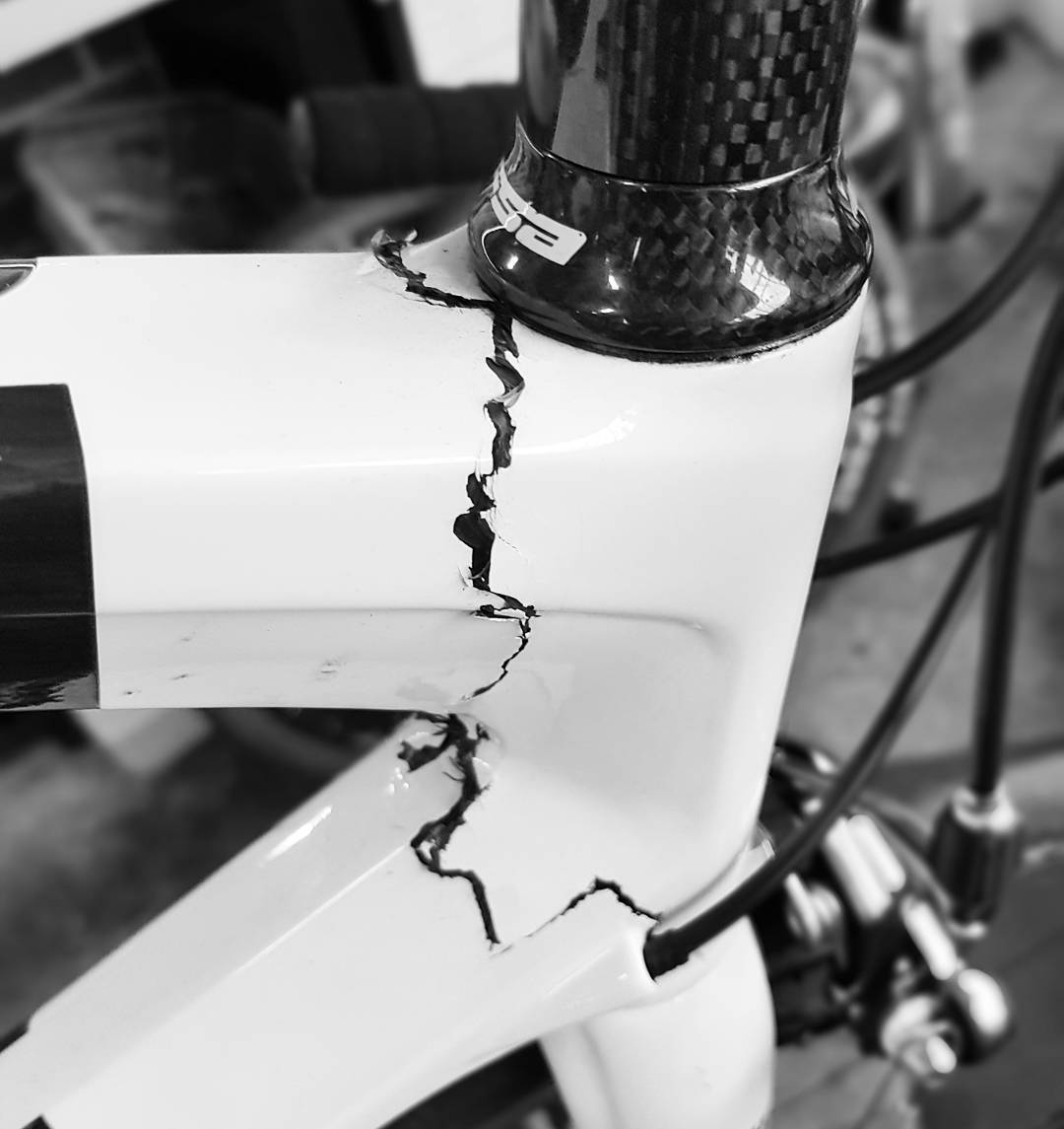
1. Headtube and Forks
- Damage Type: Front-on impact damage, such as cracks in the housing or at the downtube junction.
- Cause: Collisions, falls, or impacts during riding or transport can stress this critical area, potentially compromising the bike’s steering and stability.
2. Top Tube
- Damage Type: Impact damage, including cracks or dents.
- Cause: Improper use of bike clamps during transport or maintenance can exert excessive pressure. Additionally, handlebars rotating into the top tube during a crash or sudden movement can lead to impact marks or cracks.
3. Seat Post Clamp Slot
- Damage Type: Hairline cracks in the area around the seat post clamp.
- Cause: Over-tightening the seat post clamp or accidental impacts can weaken this area, potentially affecting the bike’s structural integrity.
4. Seat Stay (Top)
- Damage Type: Scratches or cracks near the brake mount.
- Cause: Improper brake installation, maintenance mishaps, or accidental impacts can damage the seat stay near the brake mounting points.
5. Seat Stay (Bottom)
- Damage Type: Cracks or complete snapping of the seat stay.
- Cause: Impacts, such as being hit during transport or collisions, can lead to significant structural damage in this area.
6. Bottle Cage Rivnuts
- Damage Type: Loose or ripped-out rivnuts.
- Cause: Over-tightening screws or excessive force applied to the bottle cage can damage the rivnuts, potentially affecting the bike frame.
7. Downtube
- Damage Type: Impact marks, dents, or cracks.
- Cause: Impacts from rocks, debris, or mishandling during transport are common culprits for downtube damage.
Preventing Damage
To keep your carbon fiber bike in top condition:
- Handle with care: Avoid over-tightening bolts or clamps, and use torque wrenches where appropriate.
- Protect during transport: Use padded bike covers and secure the bike properly to prevent movement and impacts.
- Regular inspections: Check for cracks, scratches, or other signs of damage, especially after falls or impacts.
- Proper maintenance: Follow manufacturer guidelines for handling and servicing, especially when installing components or accessories.
Carbon fiber bikes are a significant investment, and with proper care, they can provide years of high-performance riding. By understanding potential damage scenarios and taking proactive steps, riders can ensure the longevity and reliability of their bikes.